

The embedded image format does not support a reliable web preview. Download the approved workbook to view the complete diagram.
Download approved workbookHR CONCRETE PUMPS
HR40-5RZ
MACK Granite 64BR · SDD · WB 6,930 mm / 7,550 mm. Pending — cab-over chassis data and source omissions.
- Vertical reach
- 39.2 m / 128 ft 7 in
- Horizontal reach
- 35.2 m / 115 ft 6 in
- Rated output · rod side
- 160 m3/hr / 209 yd3/hr
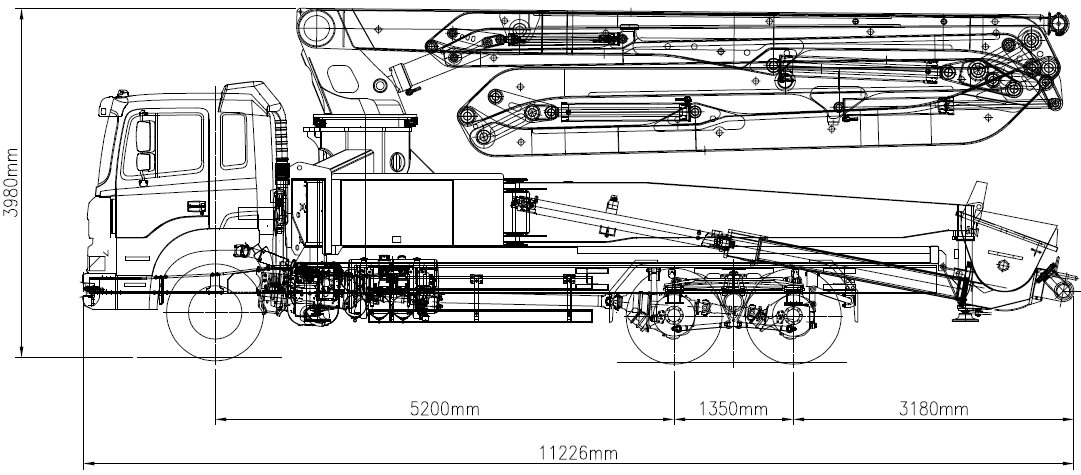
Cab-over (short-nose) chassis
DRAWINGPending — drawing to be provided.
Official drawing showing dimensions, wheelbase, total weight and weight distribution for each axle.
Conventional (long-nose) chassis
DRAWING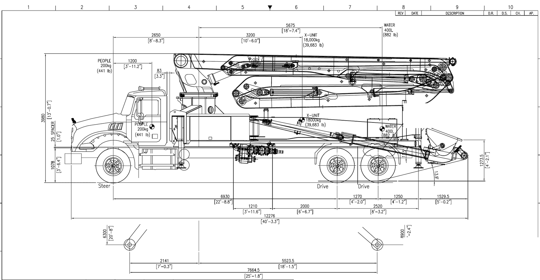
- Pump model
- HR40-5RZ
- Chassis
- MACK Granite 64BR
- Configuration
- SDD
- Wheelbase
- 6,930 mm
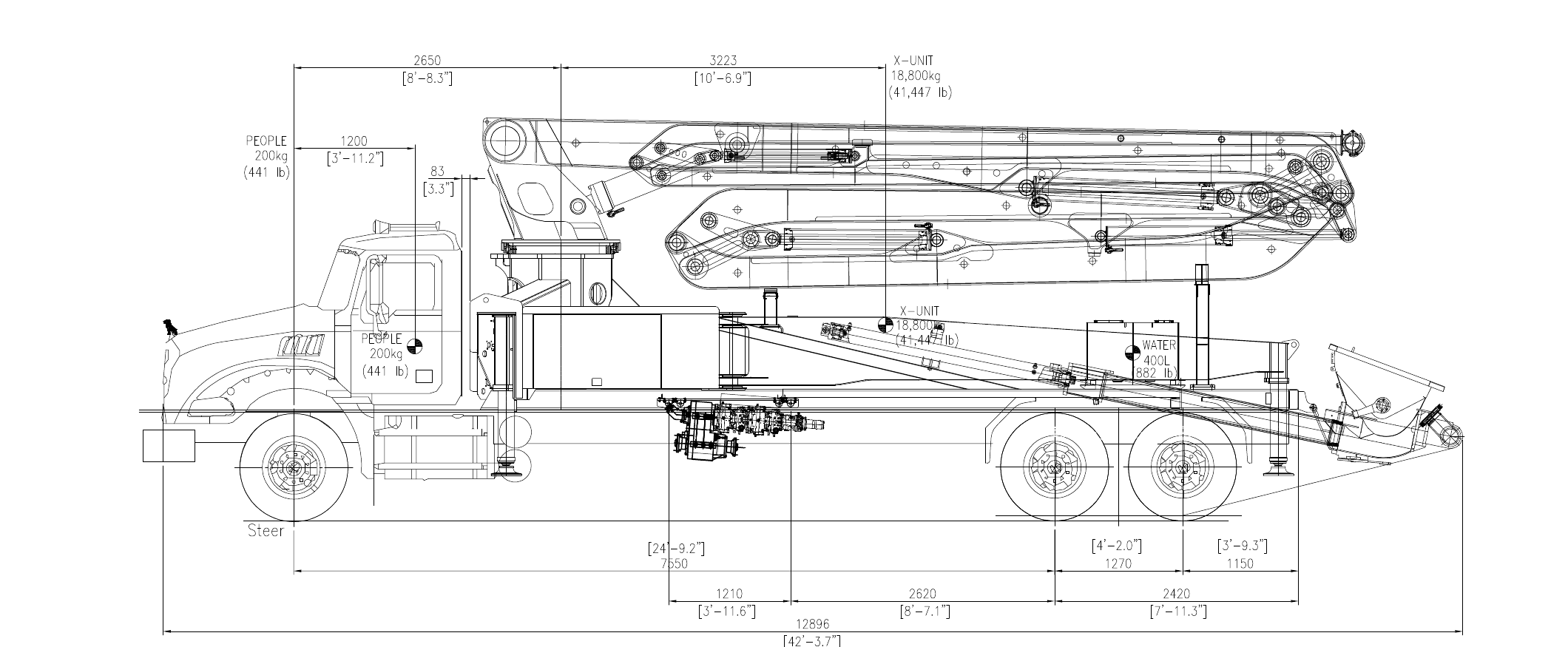
- Pump model
- HR40-5RZ
- Chassis
- MACK Granite 64BR
- Configuration
- SDD
- Wheelbase
- 7,550 mm
FULL MODEL DATA
Full specifications.
Pending — the cab-over chassis specification and fields not stated for the conventional chassis are still required.
All 54 fields shown.
Supplied pump specifications
Source: HR40-5RZ Specification.xlsx · worksheet “HR40-5RZ SPECIFICATION” · A1:I40
Swipe horizontally to view all columns.
| Specification | Metric | Imperial |
|---|---|---|
| Boom | ||
| Number of Booms | 5 | |
| Folding Type | RZ | |
| Maximum Vertical Reach | 39.2 m | 128 ft 7 in |
| Maximum Horizontal Reach | 35.2 m | 115 ft 6 in |
| Unfolding Height | 8.3 m | 27 ft 3 in |
| General | ||
| Delivery Pipe Size (Inner Diameter) | 125 mm | 5 in |
| Rotation | 370 ˚ | |
| End Hose Length | 3 m (4 m) | 9 ft 10 in (13 ft 1 in) |
| End Hose Size (Inner Diameter) | 125 mm | 5 in |
| Outrigger Spread (Front) | 6,300 mm | 20 ft 8 in |
| Outrigger Spread (Rear) | 8,600 mm | 29 ft 2 in |
| Hydraulics | ||
| Output (Rod Side) | 160 m3/hr | 209 yd3/hr |
| Output (Piston Side) | 100 m3/hr | 131 yd3/hr |
| Pressure (Rod Side) | 70 bar | 1,015 psi |
| Pressure (Piston Side) | 112 bar | 1,624 psi |
| Concrete Cylinder Size (Inner Diameter) | 230 mm | 9 in |
| Stroke Length | 2,100 mm | 83 in |
| Drive Cylinder Size (Inner Diameter) | 130 mm | 5 in |
| Rod Size | 80 mm | 3 in |
| Number of Strokes (Rod Side) | 30 / min | |
| Number of Strokes (Piston Side) | 19 / min | |
| Hopper Capacity | 600 ℓ | 159 G |
| Hydraulic System | Open-loop | |
| Hydraulic System Pressure | 350 bar | 5,076 psi |
| S-Valve | D230 x D180 (S2318) | |
| Main Pump | A11VLO260 (Rexroth) | |
| Water Tank | 400 ℓ | 106 G |
| Water Pump Pressure | 20 bar | 290 psi |
※ All technical data are theoretical values, and specifications are subject to change without prior notice due to continuous product improvement.
Values and units are reproduced from the source document without calculations or conversions.
These pump values do not establish chassis applicability. The conventional long-nose chassis data below is transcribed separately from the MACK Granite 64BR SDD source drawing; the cab-over chassis remains pending.
Chassis specifications
| Cab-over (short-nose) chassis | |
|---|---|
| Pending — specification must be provided. | |
| Chassis manufacturer and model | Pending — information to be provided. |
| Axle configuration | Pending — information to be provided. |
| Wheelbase and axle spacing | Pending — information to be provided. |
| Transport length | Pending — information to be provided. |
| Transport width | Pending — information to be provided. |
| Transport height | Pending — information to be provided. |
| Chassis-only weight distribution | Pending — information to be provided. |
| X-unit weight | Pending — information to be provided. |
| Total vehicle weight and loading condition | Pending — information to be provided. |
| Front axle load | Pending — information to be provided. |
| Rear axle / axle-group loads | Pending — information to be provided. |
| Weight distribution for each axle | Pending — information to be provided. |
| Maximum permissible axle weights | Pending — information to be provided. |
Swipe horizontally to compare both wheelbases.
| Conventional (long-nose) chassis | ||
|---|---|---|
| Specification | WB 6,930 mm | WB 7,550 mm |
| Approved source | MACK Granite 64BR SDD drawing, page 1 | MACK Granite 64BR SDD drawing, page 1 |
| Chassis manufacturer and model | MACK Granite 64BR | MACK Granite 64BR |
| Axle configuration | SDD - Steer (1); Drive (2-3) | SDD - Steer (1); Drive (2-3) |
| Wheelbase and axle spacing | 6,930 mm / 22 ft 8.8 in wheelbase; 1,270 mm / 4 ft 2.0 in drive-axle spacing | 7,550 mm / 24 ft 9.2 in wheelbase; 1,270 mm / 4 ft 2.0 in drive-axle spacing |
| Transport length | 12,276 mm / 40 ft 3.3 in | 12,896 mm / 42 ft 3.7 in |
| Transport width | Pending — information to be provided. | Pending — information to be provided. |
| Transport height | 3,980 mm / 13 ft 0.7 in | Pending — information to be provided. |
| Chassis-only weight distribution | Steer (1): 4,574 kg / 10,084 lb; combined drive group: 3,595 kg / 7,926 lb; total: 8,169 kg / 18,010 lb | Steer (1): 4,574 kg / 10,084 lb; combined drive group: 3,595 kg / 7,926 lb; total: 8,169 kg / 18,010 lb |
| X-unit weight | 18,000 kg / 39,683 lb | 18,800 kg / 41,447 lb |
| Total vehicle weight and loading condition | Calculated curb: 26,169 kg / 57,693 lb; calculated gross: 26,769 kg / 59,016 lb (people: 200 kg / 441 lb; water: 400 L / 882 lb) | Calculated curb: 26,969 kg / 59,456 lb; calculated gross: 27,169 kg / 59,897 lb (people: 200 kg / 441 lb) |
| Front axle load | Calculated steer - curb: 8,655 kg / 19,081 lb; gross: 8,783 kg / 19,375 lb | Calculated steer - curb: 9,884 kg / 21,790 lb; gross: 10,055 kg / 22,167 lb |
| Rear axle / axle-group loads | Calculated drive group (axles 2-3) - curb: 17,514 kg / 38,612 lb; gross: 17,986 kg / 39,625 lb | Calculated drive group (axles 2-3) - curb: 17,085 kg / 37,666 lb; gross: 17,114 kg / 37,730 lb |
| Weight distribution for each axle | Steer and combined drive-group values are listed above; individual drive-axle loads are not specified and the Actual rows are blank. | Steer and combined drive-group values are listed above; individual drive-axle loads are not specified and the Actual rows are blank. |
| Maximum permissible axle weights | Front: 9,072 kg / 20,000 lb; rear group: 20,866 kg / 46,002 lb | Front: 9,072 kg / 20,000 lb; rear group: 20,866 kg / 46,002 lb |
No specifications match that search. Try a broader term.
Conventional long-nose chassis values are copied from the approved source drawing. Source conflict: the metric heading identifies the drive group as axles 2-3, while the imperial heading identifies it as axles 3-4. The source provides only the combined group load, not individual axle loads. Pending fields are not stated in the source, and no chassis data is inferred from the pump specifications.
MACHINE OVERVIEW
Read the machine at a glance.
Pending — information to be provided.
Client-approved component descriptions and illustrations for HR40-5RZ are required.
OPERATING ENVELOPE
Working range.
TECHNICAL DOCUMENTS
Technical documents.
XLSX
HR40-5RZ Approved specification
HR40-5RZ Specification.xlsx
Includes the complete specification table, dimension drawing, and working range diagram.
Download approved workbook※ Subject to change depending on the chassis specifications.
Keep exploring.
All concrete pumpsMODEL INFORMATIONHR21-4ZRVertical reach: 21.2 m / 69 ft 5 inMODEL INFORMATIONHR28-4ZVertical reach: 27.5 m / 90 ft 3 inMODEL INFORMATIONHR32-5ZVertical reach: 31.4 m / 103 ftMODEL INFORMATIONHR38-5ZVertical reach: 37.6 m / 123 ft 4 inMODEL INFORMATIONHR40-5RZVertical reach: 39.2 m / 128 ft 7 inCurrent modelMODEL INFORMATIONHR42-5RZVertical reach: 41.6 m / 136 ft 6 inMODEL INFORMATIONHR43-5RZVertical reach: 42.2 m / 138 ft 5 inMODEL INFORMATIONHR56-5RZVertical reach: 55.2 m / 181 ft 1 in